Second Generation Nissan Xterra Forums banner

2011 Xterra Fog Lights and Off Road Lights Rewire

75K views 106 replies 38 participants last post by  thescher  
#1 ·
I traded in my 2007 for a 2011 PRO-4X a few weeks ago and the lights have been driving me nuts. I set out to make the fogs work any time the tail lights were on and the off road lights work any time the ignition was on. However, I also wanted to keep the look of the vehicle stock an not bypass any of the major safety features or over load any circuits. Having a background in electrical engineering helped, but I can't thank you guys enough for the help you've given here. As such, I thought I would share my electrical modifications since I don't think anyone has posted modifications that keep all of the safety features in place.

First, with the exception of the fog lights and the trailer lights, the lighting and electrical wiring diagrams in the 2009 factory service repair manual are accurate for the 2011. (http://pdf.textfiles.com/manuals/AUTOMOBILE/NISSAN/xterra/2009_Xterra/ EXL.pdf is where the lighting diagrams are).
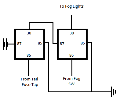
Fog lights mod:

To really make this work the way I wanted, I combined the following two mods:
http://www.clubfrontier.org/forums/f23/fog-light-pass-2991/
http://www.thenewx.org/forum/showthread.php?t=41057

I don't like how the first is an "always on" sort of thing nor do I like that it loads a previously 10A circuit with up to 25A. So, I used the fuse tap to give me a positive voltage when the tails were on and I used the stalk mod to let me know when the switch was on (note, I wired a positive voltage to the stalk instead of a ground). The resulting circuit was two relays in series wired directly to the battery and the fogs (I actually wired it to the fog lights circuit in the fuse box).

Image


Off Road Lights mod:

This took a lot more work. I originally started with http://www.thenewx.org/forum/showthread.php?t=30851 however, I really don't like that this bypasses the cover sensor and doesn't use the stock switch (again, I really wanted to keep the stock equipment). With a little bit of work, I was able to solve both problems.

Using a flip flop circuit, you can utilize the (negative/ground) pulse sent by the stock momentary switch.

After a fair amount of testing, I found that the cover sensors will ground their circuit to the BCM when the covers are on. Using this and another relay, I was able to create a circuit that obeyed all of the safety features and didn't require severing the wiring harness (I was able to tap in using wire taps).

Image


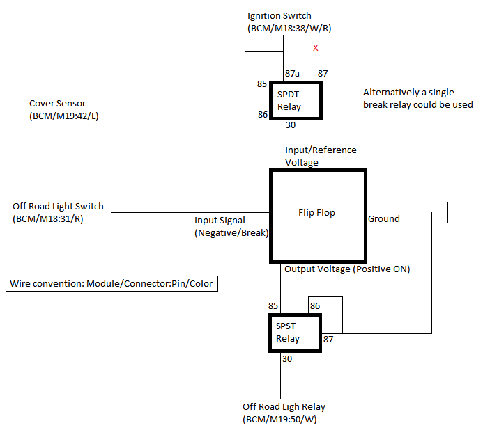
Note: It is intentional that the Ignition +12V is wired to 87a (normally closed). This is so the cover sensors can break the circuit when they're on.

A digital/IC flip flop (a pulse SR Latch or equivalent) can be used since the currents are minimal, however, I like the idea of a mechanical switch instead just to make sure melt downs wouldn't cause a back current. I found this http://www.the12volt.com/relays/relaydiagram23.html and it worked great.

I would post pictures, however, the links I gave really already give you everything you need and the pictures of the BCM and wiring harnesses weren't useful at all. If you go for the off road lights mod, make sure you study the diagrams in the manual, particularly page EXL-73 and the pinout description starting on EXL-109. Thanks again for making such a helpful community. I hope this is able to help someone else with the same concerns I had.
 
#3 ·
I really have no idea what you just said, but it sounds very good. I will try to translate at some point into laymanspeak since I would like to change the behavior of the fogs and OR lights at some point.
 
#7 ·
newbie with wiring questions

Hi everyone, I'm new to this forum. I just got my 2011 Pro-4x Xterra about a month ago and have been spending waaay too much time on this forum planning the mods. Thanks to all of you for sharing your mod ideas. It's been a busy mod month.

theascended, first of all, thanks for taking the time to do this. :notworthy: I'm about ready to jump into this mod this weekend but I just had a couple questions before I start that I was hoping you'd be able to answer.

For the roof lights:

  • In your wiring diagram, there's a red "x" on the SPDT relay. I'm assuming this means it's not used. Is that correct?

  • In the wiring diagram for the flip flop (http://www.the12volt.com/relays/relaydiagram23.html), with the left-most relay as #1 and the right-most relay as #4:

    [*]What's the black rectangular (with stripe) symbol/object wired to relay #1, terminal 87a?​
    [*]There's a similar symbol/object on relay #2 between terminals 86 and 85. Is terminal 87a involved in the wiring of this?​

  • Is it just the 4 wire taps coming from the BCM wires to connect into the relay assemblies?

Thanks again.
 
#12 · (Edited)
Hi everyone, I'm new to this forum. I just got my 2011 Pro-4x Xterra about a month ago and have been spending waaay too much time on this forum planning the mods. Thanks to all of you for sharing your mod ideas. It's been a busy mod month.

theascended, first of all, thanks for taking the time to do this. :notworthy: I'm about ready to jump into this mod this weekend but I just had a couple questions before I start that I was hoping you'd be able to answer.

For the roof lights:

  • In your wiring diagram, there's a red "x" on the SPDT relay. I'm assuming this means it's not used. Is that correct?

  • In the wiring diagram for the flip flop (http://www.the12volt.com/relays/relaydiagram23.html), with the left-most relay as #1 and the right-most relay as #4:

    [*]What's the black rectangular (with stripe) symbol/object wired to relay #1, terminal 87a?​
    [*]There's a similar symbol/object on relay #2 between terminals 86 and 85. Is terminal 87a involved in the wiring of this?​

  • Is it just the 4 wire taps coming from the BCM wires to connect into the relay assemblies?

Thanks again.
Sorry Bud! Almost missed your first post.

- Yes, the red X is NOT connected.
- The symbol is a diode. I think you already figured that one out :)
- No, on that particular relay, nothing should be attached to 87a. In general, on the diagram I linked to, the connection points are identified with a small circle.
- I used 4 wire taps: Ignition, ORL SW, cover sensor, ORL relay. Ground can also be tapped into but there are a few chassis screws close.
 
#8 · (Edited)
Hey... I like the mod.
I didn't see your thread and I started this.
http://www.thenewx.org/forum/showthread.php?t=47702

I have similar idea, except mine I prefer to have the fog lights automatically on when I use the roof lights. It's obvious that when we use the roof lights we want more lights.
But while having the roof lights off, I still want to be able to use the stock switch for the fog lights too.

theascended - since you have a lot more electrical knowledge than me, do you think my little diagram of the 2 funnels and goal posts would work? lol


EDIT: See post 46 for picture tutorial.
Image
 
#10 ·
Hey... I like the mod.
I didn't see your thread and I started this.
http://www.thenewx.org/forum/showthread.php?t=47702

I have similar idea, except mine I prefer to have the fog lights automatically on when I use the roof lights. It's obvious that when we use the roof lights we want more lights.
But while having the roof lights off, I still want to be able to use the stock switch for the fog lights too.

theascended - since you have a lot more electrical knowledge than me, do you think my little diagram of the 2 funnels and goal posts would work? lol
Hey Wasabi4ever. A couple questions for you. 1) Do you want the ORL switch to work independent of the high beams? 2) Are you planning on running your own wires/switches?

The diagram you have setup will require you to rewire the fogs and the ORL since they're all currently controlled through the BCM. The ORL relay is under the dash so you can get away with some taps, but the fogs are controlled entirely within the BCM and requires some sort of bypass to make it work.

If you at least do the fog light mod using the later diagram (only 1 relay) there is an easy way you can do what you want. Since my fog mod and in the ORL wiring are both ground activated all you need to do is jump the relay trigger for the ORL (BCM/M19:50/W) to pin 86 on the new fog relay from the mod. The same method will work if you do both mods as well.
 
#9 ·
OK, so after poking around, I found this. Those symbols/objects would appear to be diodes. So the remaining question is what voltage and amperage diodes were used? I'm assuming the voltage is 12 and the amperage will be minimal but I just want to make sure before I go hacking in my new X. Thanks.
 
#11 ·
Hey kingruc,

Yes, those are the diodes you are looking for! I'm going to answer your question a bit more completely just in case someone else might have a similar question.

I used all 12V relays. This will be required since the voltage rating on the relays is actually the Vdrop needed to activate the relay (not the max V the relay can take) and the batter will put out at least 12V (usually closer to 14V).

As far the the amps go, the fog light mod requires at least a 15A relay, thought I would go to around 20 just to make sure you have some running room on the parts. Make sure to put a 15A fuse somewhere in the power circuit (pin 87 or pin 30) so that you can't burn up your wiring harness.

The ORL mod doesn't need high amp relays since you're playing with signal voltages. I used 1A microcontroller relays to make the flip-flop circuit and a .5A relay for the ORL cover cutoff. You really should keep the amp ratings the same, but I didn't have a choice at the time. I did intentionally use a 2A/12V diode in the circuit to protect against heat in the backwards voltage direction.
 
#14 ·
Sorry to interrupt, but I have this question. I currently have 4 pairs of fog lights connected to my truck using separate relays as shown here: http://www.classictruckshop.com/clubs/earlyburbs/projects/bosch/foglites.htm

however, connector #85 goes from the switch tapped to the front parking lights. Would I have problems having all 4 pairs of lights tapped into that parking light??? I'm assuming that the stock cable for the parking lights are very thin but then I don't know how many amps or power the switch to each relay would withdraw??? I did blow the 10amp fuse the parking lights come with and just put a 20amp fuse which has held well for the past year or so.. but always just worried it might melt some cable somewhere???
 
#16 ·
Pin 85 and 86 on a relay are low amp signal circuits. When there is a voltage drop across 85-86, the relay is triggered and a connection is made between 87 and 30 (in a SPDT relay 87a is connected to 30 when there is no voltage drop across 85-86). Using a fuse tap from the tails and connecting to 85 is perfectly safe.
 
#18 ·
SUCCESS!!! :wav:

Thanks so much theascended! I couldn't find a 12V/2A diode so I got this one instead. The soldering of the relays took awhile but it's all in there and working now!

Just put HID in the fogs and roof lights last weekend (did the headlights about 3 weeks ago) and cannot wait to get on the trail again and have all three sets on at the same time.

Just awesome. Thanks again!
 
#21 ·
AWESOME kingtruc! Please post a pic (and give some details on the HIDs - I've been looking at fog and ORL replacements too).
Unfortunately, the joy was short-lived.

The roof lights worked fine when I tested them last night. This morning, I turned on the lights again but then, while they lights were still on, I put the covers on to see if they would turn off. They turned off but then wouldn't turn on again right after I took the cover off and hit the switch. This was all done with the key turned to On and no other lights on. Now, the switch works intermittently and only when the engine is off. I guess I'll be trying to troubleshoot this week and I guess I found that reason to go get a better multimeter after all.

Troubleshooting and observations so far:
  • I can turn on the roof lights and start the engine but after about 5 seconds, the lights turn off.
  • Putting the covers on the lights now does not turn off the lights.
  • I was expecting all the BCM wire taps to be 0V when the key is turned to Off but one of them was hot (I think it was the one for the roof light switch which I thought was weird).
  • After turning the key to On, I have to wait a couple seconds before I can hit the roof light switch or else nothing happens. I'm assuming this is because the car system is going though its checks and some of the BCM wire taps are not ready yet.
  • I had assumed that since this was done with BCM wire taps, that removing the mod relay assemblies would have allowed the roof lights to operate per OEM functionality, i.e. roof lights can be turned on when high beams are on. But even this doesn't work now.
  • I swapped out each of the 6 relays to make sure I didn't have a bad one in there and there was no noticeable difference.

I'll check the service manual again and see what values are supposed to be coming out of the BCM wire taps. I'm hoping to get this figured out before I hit the trail again in two weeks.

In the meantime, here are a couple pics to show that it worked.

Wasabi4ever, that Plasti-Dipped grill emblem was courtesy of your write-up. Did all the ones on the back door too. Now it doesn't look like I'm driving around with Nissan bling all over my X. Thanks. Contemplating doing the silver grill parts too (never did like the 2009+ grills).

theascended, I got conversion kits from Kensun for all three sets of HIDs. I started with the 6000K in the headlights and then I got the 5000K for the fog and roof lights. I just ordered the 5000K replacement bulbs for the headlights. The 6000K are nice but it makes highway reflectors and signs ridiculously (almost dangerously) bright. I'm hoping the change in color temperature is going to make the brightness a more manageable color. The headlights alone will light up the new road reflectors just about as far as the eye can see and I mean they're LIT UP. They're all the 35W conversion kits and you can find them on Amazon or eBay.

Here are the ones I got:
Headlights (9007 bi-xenon 6000K)
Fog lights (H11 5000K)
Roof lights (9005 5000K)

They don't turn on as fast as OEM HIDs but they're just as bright. I love 'em. When I get this mod working, it's going to be a wall of HID light. I'll post the pics once the mod works and I get out to the trails.

Engine off, key turned to On

Image


Wall of HID light

Image
 
#26 ·
Thanks!!
It will look better with stealth grill and don't forget the rims :)
Still debating the grill but I won't be doing the wheels. I'm not crazy about the machined wheels but I think the only thing I'd do to them is do a clear coat dark gray.


Wasabi, I did answer your PM, however, I'll post here for anyone else reading.

I wish I had seen this in your last post. The problem is very likely the zener diode. Zeners work like normal diodes until the back voltage reaches a threshold (breakdown). Once the voltage hits that point, current is allowed to flow in the backwards direction. Since you bought a 12V zener, you are almost certainly hitting that limit since our battery is nominal around 14V.
Thanks, theascended. That was me who PM'd you. I'll be working on it this week. I live in San Francisco and don't have a garage to work on my X so it's, er, challenging. I'll post back when it's working. It's been a crash course in relays, diodes and BCM wiring since I read your original post several weeks ago.

Cheers
 
#23 ·
Wasabi, I did answer your PM, however, I'll post here for anyone else reading.

I wish I had seen this in your last post. The problem is very likely the zener diode. Zeners work like normal diodes until the back voltage reaches a threshold (breakdown). Once the voltage hits that point, current is allowed to flow in the backwards direction. Since you bought a 12V zener, you are almost certainly hitting that limit since our battery is nominal around 14V.
 
#27 ·
I'm happy to report that the lights are working. The multimeter confirmed the cover sensor was still putting out voltage even when the cover was off when it should be 0V. I'm guessing it was due to my putting the cover back on with the lights still on. So for the time-being, I just disconnected the cover sensor wire tap into the relay assembly from theascended's wiring diagram.

Thanks, theascended, for the legwork and help on this. By the way, theascended is right and it's relatively straightforward if you follow the diagrams he provided (and I didn't even know what a relay was or did a month ago). Whatever you do, don't put the light covers back on while the lights are still on. :cussing:
 
#25 ·
:) The tools are pretty minimal. I got all of this done with a soldering iron, a couple of screw drivers, a wire hanger (to fish through the firewall) and some angle cutters (aka dikes). The key is to take your time and verify your setup.

I'm happy to answer any questions you may have, unfortunately NC is a long way from TX.
 
#30 ·
So, I really don't have the electrical know-how or even know how to read all the symbols. Is there a way I can do this without having to take an electrical engineering class.

Just to be clear what the mod is...I would be able to turn on my fogs independently of my headlights and my off-road roof lights independent of the headlights (no need for highs to be on to use ORLs)
 
#31 ·
Correct on both assumptions. With this mod, the fog lights will work with the stock switch on the stalk but will be available any time the tail/parking lights on on. The ORLs will be available any time the ignition is in the on position (can't get around this without a much larger rewire).

As for the symbols and diagrams, I'll answer any questions you have to simplify things. The only symbols on the diagrams really is the capacitor (the small rectangle with a stripe) and the symbol for ground (the stripes in a triangular pattern). Other than that, feel free to ask.
 
#32 ·
Ok. So could you make a list of the things that I would need to buy for this rewire? I see that a couple posts from your original you made a correction and made a simpler setup for the fogs. So I'll follow that one along with the first ORLs wiring.

I understand the numbers are the "labels" for the wires, but where do I find them. Is this something I look for off the fuse box? I don't even know where that is actually (I just bought the truck september 13th and haven't gone through every nook and cranny yet.)

I don't want to be a pain, but maybe pictures of how you did this? I know I'm not the only one that wants to have a clean rewire like this to stock switches.

I really appreciate the help, I had to scrape money from all my accounts to get this truck, that's why I'm a little timid about cutting things right now.
 
#33 · (Edited)
Ok. So could you make a list of the things that I would need to buy for this rewire? I see that a couple posts from your original you made a correction and made a simpler setup for the fogs. So I'll follow that one along with the first ORLs wiring.
For the fog light rewire, using the 2nd diagram:
-1 SPST (single pole, single throw) relay, 12 V and minimum 20A
-1 Fuse Tap/Add a circuit
-1 inline fuse with a 15A fuse to match
-Around 20 FT #12 gauge wire (you'll probably use less but its better to have extra than stretch it too far)
-A soldering iron and solder (you can wire without, but its better to make your connections at least on the relay permanent, this can also be accomplished if you can find a relay with a socket that has screw terminals)
-All of this can be found at something like Auto Zone

For the ORLs:
-5 SPDT (single pole, double throw) relays, 12V and 1A should be enough
-1 SPST relay, 12 and 1A should be enough
-2 2A diodes (higher amp is fine)
-10 ft or so of #16 gauge wire, 12 gauge will also work, its just thicker
-4 wire taps
-Soldering is highly recommended to make the flip-flop, otherwise you'll run a high risk of it coming apart
-All of this can be found at Radio Shack

I understand the numbers are the "labels" for the wires, but where do I find them. Is this something I look for off the fuse box? I don't even know where that is actually (I just bought the truck september 13th and haven't gone through every nook and cranny yet.)
I mention my label convention on the diagrams. The wire color definitions can be found here: http://pdf.textfiles.com/manuals/AUTOMOBILE/NISSAN/xterra/2009_Xterra/GI.pdf on page GI-10. The location of the connectors and BCM can be found in a few places:
http://pdf.textfiles.com/manuals/AUTOMOBILE/NISSAN/xterra/2009_Xterra/PG.pdf (PG-37 should catch most of the harnesses you're looking for)
http://pdf.textfiles.com/manuals/AUTOMOBILE/NISSAN/xterra/2009_Xterra/EXL.pdf (EXL-73 starts the ORL section diagrams, which were exceedingly helpful for me, pay attention to EXL-74 as it tells you what color the connectors are into the BCM and gives you a pin diagram of each connector)

For the fog lights, you'll be working on left side stalk of the steering wheel and in the fuse box under the hood.

The BCM is where you'll be making all of your additions for the ORL and is located underneath the steering wheel on the right side of the drivers side compartment. There will be 3 connectors/harnesses going into it and you'll be taping into 2 of them.

I don't want to be a pain, but maybe pictures of how you did this? I know I'm not the only one that wants to have a clean rewire like this to stock switches.
I wish the pictures I had taken were useful. Most of them came out grainy and had no points of reference to make them useful to anyone. For the Fog lights mod, there are great pictures in the stalk light mod that I linked to and that will get you most of the way. My mod makes the stalk light mod work with an '11 and makes the circuit much safer. The ORL mod isn't hard once you are able to get the flip flop together and find the BCM. I personally spent over an hour double checking the harnesses and making sure I was taping the right wires, but in the end all you're doing is finding 4 wires, taping them and then finding a ground screw.

I really appreciate the help, I had to scrape money from all my accounts to get this truck, that's why I'm a little timid about cutting things right now.
A wealthy person who bought it on a whim should be weary of cutting things :) Screwing up the wiring is an expensive proposition and you want to do it right. Being timid about it means you'll be careful and double check your work, thats a good thing.
 
#36 ·
Thanks theascended, I may just be over thinking this a little. I had a 2007 VW Rabbit prior to my X and had to look at wiring diagrams from the factory to figure out what wires to tap, not as in depth, but I'm feeling a little more confident now.

Now all I have to do is find the time to do this. I've been working 7 days a week for over a year now and it's hard to find time for anything! I guess it gives me time to save some money for mods though!
 
#38 ·
I have postpone the installation of my fog lights for next week due to the weather this weekend is going to be -27*c. Even though I have a garage but it's not heated so I don't want to get frostbite.
However I have everything prepared and ready to install. The only thing is to loop the wiring through the firewall, so who knows I might just do it anyway. We'll see.


I have an off topic question. While inspecting the fuse box to familiar myself with it before diving in with the mod, I noticed this relay in there which doesn't look like it belong there but rather was added afterward. I purchased the X brand new with 30km on it so I know nobody tampering with it before me.
My guess is this is for the roof lights relay which perhaps was later added? They relay tapped into a few wire harness. What is it? and why Nissan do this? Doesn't look very "factory" like.


This relay:
Image


Here are the wires they tapped in.
Image

Image